While torque and speed are critical factors to consider when sizing motors, another crucial aspect is load inertia. Have you ever pondered why racing bikes and mountain bikes differ so much in wheel design? Racing bikes feature lightweight, narrow wheels, reducing their moment of inertia, which makes peddling slightly easier. In competitive racing, even small advantages can make a significant difference.
Inertia, derived from the Latin word "iners," meaning sluggish or idle, refers to an object's resistance to changes in its velocity. The greater the inertia, the more force required to accelerate or decelerate it. When it comes to rotational motion, load inertia, or moment of inertia, represents the resistance of an object to changes in its speed relative to the axis of rotation. It’s essentially the product of an object's mass and the square of its perpendicular distance from the axis. Load inertia is commonly denoted as "J."
Manufacturers usually provide permissible load inertia or inertia ratio values to aid in motor selection. Permissible load inertia values are generally listed for AC and brushless motors, while inertia ratios are specified for stepper or servo motors. These ratios are obtained by dividing the total load inertia by the motor's rotor inertia. Exceeding these values can lead to missed steps, stalling, or vibrations. Closed-loop motors tend to tolerate higher inertia ratios compared to open-loop motors.
For instance, let's consider the following recommended inertia ratios for various motor types:
| Motor Type | Frame Size (mm) | Frame Size (NEMA) | Inertia Ratio |
|------------|-----------------|-------------------|---------------|
| Open-Loop Stepper Motors | 20, 28, 35 | 8, 11, 14 | 5:1 or less |
| Open-Loop Stepper Motors | 42, 50, 56.4, 60, 85 | 17, 20, 23, 24, 34 | 10:1 or less |
| Closed-Loop Stepper Motors | N/A | N/A | 30:1 or less |
| Servo Motors (Auto Tuning) | N/A | N/A | 50:1 or less |
| Servo Motors (Manual Tuning) | N/A | N/A | 100:1 or less |
It’s important to note that these values serve as guidelines. While exceeding them isn’t ideal, certain setups might allow for such deviations. A case in point is a project involving slot machines where a team utilized a stepper motor despite exceeding the permissible inertia ratio. By employing a carefully designed motion profile with gradual acceleration and deceleration, along with rigorous testing, they managed to make the system function effectively.
Calculating load inertia involves understanding the fundamental equation for inertia (J):
\[ J = m \cdot r^2 \]
where \( m \) is the mass of the object and \( r \) is the perpendicular distance from the axis of rotation. Simplified formulas exist for common objects like cylinders, hollow cylinders, rectangular objects, and objects moving linearly. Depending on the shape of the object and the available data (such as weight or dimensions), you can select the most appropriate equation.
Units of inertia are typically expressed in terms of ounces-inches squared (oz-in²) or ounces-inches-seconds squared (oz-in-sec²). While theoretically inertia should only involve mass, practical measurement often necessitates including gravity, leading to the use of oz-in².
To perform these calculations, additional information such as material density might be required. This is essential for determining an object's weight. For reference, here are common material densities:
| Material | Density (lb/in³) |
|----------|------------------|
| Aluminum | 0.0975 |
| Steel | 0.283 |
| Wood | 0.036 |
Suppose you’re working on a conveyor system. To calculate the total load inertia, you’ll need to sum up the inertias of all components driven by the motor, including the load, the belt, and the rollers. This requires applying two different equations.
For example, consider the following conveyor setup:
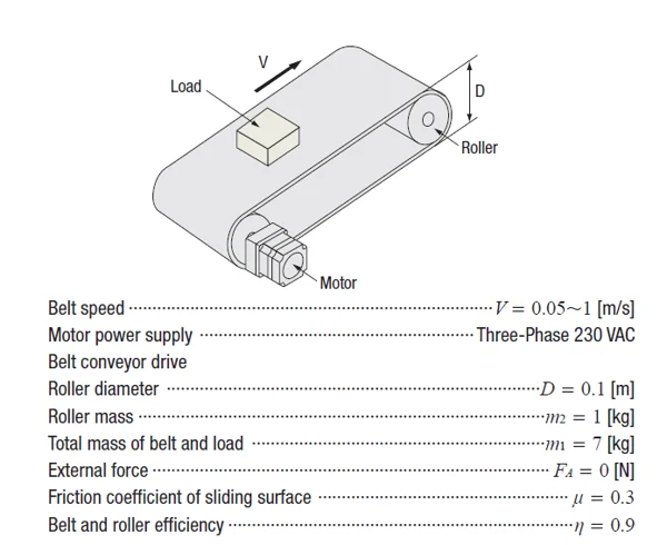
You’ll need to compute the inertia contributions from multiple components and apply the relevant formulas accordingly.
If you’re dealing with high load inertia, a geared motor offers a straightforward solution. The load inertia is reduced by the square of the gear ratio, resulting in the reflected load inertia, which represents the load inertia seen at the motor shaft.

For further insights into using gearheads to manage load inertia, especially with stepper motors, refer to our white paper.
Once you’ve computed your total load inertia, finding a suitable motor becomes easier. For instance, here’s an example of permissible load inertia values for a BLE2 Series 200/400W brushless motor:
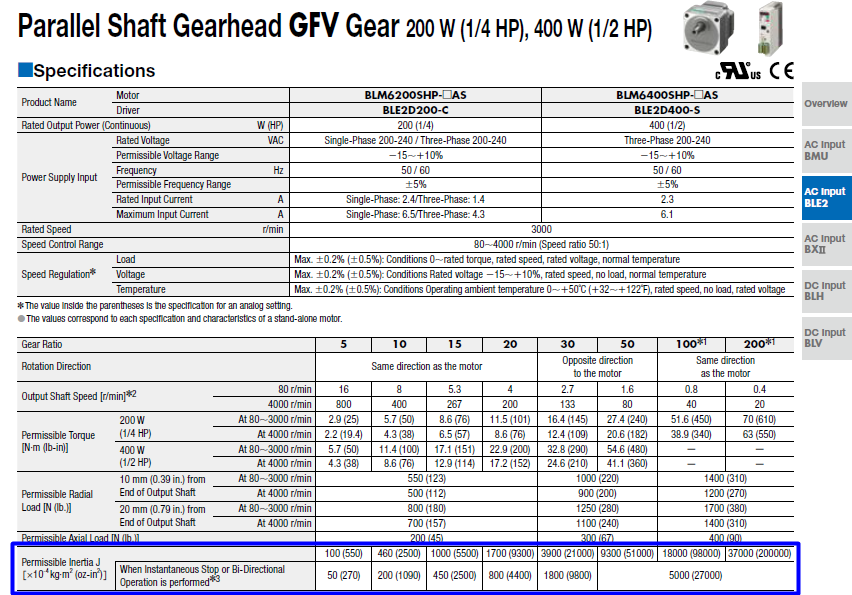
These values are already calculated for each gear ratio, so you don’t need to recalculate them. Try to avoid exceeding these limits to ensure reliable motor performance.
For stepper or servo motors, permissible load inertia values aren’t always publicly available, so relying on recommended inertia ratio guidelines is advisable.
In conclusion, load inertia is one of three key calculations necessary for proper motor sizing—alongside torque and speed. In the next installment, we’ll explore how load inertia influences acceleration torque, a critical factor in determining the total torque requirements for an application.
Need a quick refresher? Check out our comprehensive motor sizing white paper [here].
Stay tuned for the next post, where we’ll delve into calculating acceleration torque, RMS torque, and speed.
*Tip:* Accurate data is paramount in motor sizing. The more precise your inputs, the smaller the safety factor needed. Real-world applications often involve uncertainties, so strive for the best possible estimates.
Full Closed Cabin Scooter,Full Colosed Tricycle,Full Closed Scooter,Cabin Scooter
YUMBOMOBILITY LTD , https://www.yumbomobility.com